


Next: Treatment of experimental deficiencies
Up: PRODUCTION OF LINEARLY POLARISED
Previous: Introduction
Using energy and momentum conservation of the bremsstrahlung process a decomposition of the involved momenta
with respect to the incident electron momentum in longitudinal ql and transversal qt components
permits the formulation of kinematical limits for the momentum transfer  :
:

This momentum transfer range, depending on the electron energy E0 and relative photon energy x=k/E0,
is referred to as the `pancake' due to its large lateral extension (
 ).
Calculating the bremsstrahlung cross section[3,4] but
retaining the photon polarisation
).
Calculating the bremsstrahlung cross section[3,4] but
retaining the photon polarisation
 ,
the following asymptotic term is obtained:
,
the following asymptotic term is obtained:
 .
This shows that the cross section drops in first order with 1/k and that the maximal linear polarisation,
with
.
This shows that the cross section drops in first order with 1/k and that the maximal linear polarisation,
with  being the azimuthal angle of
with respect to the scattering plane, is found in that plane.
When employing an amorphous radiator, the electron scatters off a single atom which means that
the momentum transfer
being the azimuthal angle of
with respect to the scattering plane, is found in that plane.
When employing an amorphous radiator, the electron scatters off a single atom which means that
the momentum transfer  may lie at any point in the pancake leading to an isotropic distribution
of
,
hence to an unpolarised beam.
In contrast to this incoherent contribution an additional process can be observed
in crystal radiators due to their regular structure:
Whenever the momentum transfer coincides with a reciprocal lattice vector
may lie at any point in the pancake leading to an isotropic distribution
of
,
hence to an unpolarised beam.
In contrast to this incoherent contribution an additional process can be observed
in crystal radiators due to their regular structure:
Whenever the momentum transfer coincides with a reciprocal lattice vector
 the recoil is absorbed by the whole lattice enhancing the yield by coherently adding the contributions
of each atom.
Also the momentum transfer is fixed in space which therefore leads to a polarised photon beam.
Raising the photon energy x increases the coherent contribution and polarisation monotonically as well as qlwhich depends like qt on the orientation of the crystal
the recoil is absorbed by the whole lattice enhancing the yield by coherently adding the contributions
of each atom.
Also the momentum transfer is fixed in space which therefore leads to a polarised photon beam.
Raising the photon energy x increases the coherent contribution and polarisation monotonically as well as qlwhich depends like qt on the orientation of the crystal
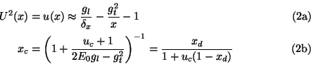
 (fig. 2 and eq. A2) and leads to a discontinuity at
 ,
where a given lattice vector does not satisfy the pancake condition anymore and thus no longer contributes
to the coherent bremsstrahlung spectrum.
The total cross section of a crystal[5,6] is a sum of coherent and incoherent (including electron-electron)
bremsstrahlung where the Debye-Waller factor
,
where a given lattice vector does not satisfy the pancake condition anymore and thus no longer contributes
to the coherent bremsstrahlung spectrum.
The total cross section of a crystal[5,6] is a sum of coherent and incoherent (including electron-electron)
bremsstrahlung where the Debye-Waller factor
![$f_{\text{Deb}}(q^2) \in [0,1]$](img19.gif) ,
which is a function of temperature
and crystal properties, governs the fractioning into coherent and incoherent contributions to the total cross section.
After introducing the intensity I per atom in units of
,
which is a function of temperature
and crystal properties, governs the fractioning into coherent and incoherent contributions to the total cross section.
After introducing the intensity I per atom in units of
 Z2mb
the cross section and polarisation P are expressed as a sum over lattice vectors
Z2mb
the cross section and polarisation P are expressed as a sum over lattice vectors  of the functions
 (eq. A1) and read in common notation:
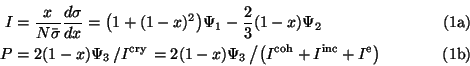
In the coherent contribution due to kinematical constraints for a given lattice vector the photon polar angle
 is a function of photon energy (eq. 3a),
apart from a negligible dependence on the azimuthal angle[4].
Collimating the photon beam enhances the ratio of coherent to incoherent bremsstrahlung,
thus increasing the degree of polarisation. Whereas the incoherent cross section is reduced approximately by
fc = uc/(1+uc) using a collimation angle of Uc (note: u=U2),
the coherent one stays unaffected in the energy range
is a function of photon energy (eq. 3a),
apart from a negligible dependence on the azimuthal angle[4].
Collimating the photon beam enhances the ratio of coherent to incoherent bremsstrahlung,
thus increasing the degree of polarisation. Whereas the incoherent cross section is reduced approximately by
fc = uc/(1+uc) using a collimation angle of Uc (note: u=U2),
the coherent one stays unaffected in the energy range
![$x(\vec{g}\,) \in \left[x_c,x_d\right]$](img25.gif) but
vanishes elsewhere:
but
vanishes elsewhere:
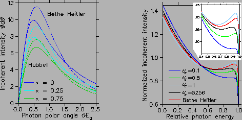
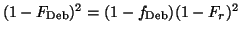
For the incoherent contribution instead of using the Bethe-Heitler cross section (eq. 3BSb in ref.[7])
the Hubbell[8] cross section derived from the Schiff cross section (eq. 3BSe),
which has a more accurate dependence on photon energy, radiator charge Z and collimation angle ucwas employed (see eq. A3 and fig. 1).
Figure:
Comparison of Z, photon energy and collimator angle Uc dependence of Bethe Heitler and Hubbell intensity.
In the right panel the intensity was normalised to unity whereas in the insert the intensity was set to one
at the origin (I(0)=1) for the sake of comparison.
 |
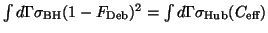
For a calculation of the incoherent contribution from a crystal radiator compared to an
amorphous one, the Debye Waller factor
 has to be taken into account, which leads to a modified
form-factor:
has to be taken into account, which leads to a modified
form-factor:
 denoted by
 .
Here Fr means a realistic carbon form-factor from a Hartree Fock calculation[9].
Due to the fact that an analytical integration of the Schiff cross section as performed by Hubbell
for the dipole form-factor with screening constant C (eq. A3) seems no longer feasible,
two approximate treatments were investigated[4].
The use of an effective screening constant seemed superior because in addition the temperature dependence of
.
Here Fr means a realistic carbon form-factor from a Hartree Fock calculation[9].
Due to the fact that an analytical integration of the Schiff cross section as performed by Hubbell
for the dipole form-factor with screening constant C (eq. A3) seems no longer feasible,
two approximate treatments were investigated[4].
The use of an effective screening constant seemed superior because in addition the temperature dependence of
 is easier implemented there.
The screening constant
is easier implemented there.
The screening constant
 for the Hubbell cross section was determined via a fitting procedure
for the total intensity
for the Hubbell cross section was determined via a fitting procedure
for the total intensity
 with
with
 ,
resulting in
,
resulting in
 for
the amorphous and 33 for the incoherent intensity.
for
the amorphous and 33 for the incoherent intensity.
Also an improved description[10] of the electron-electron bremsstrahlung Iewas used, which takes into account the binding energy of the radiator electrons
and which has a non trivial Z and photon energy dependence, see (eq. A4).
For this contribution the asymptotic Bethe-Heitler angular distribution
f(U) = U/(1+U2)2, which leads to the collimation reduction factor fc (s. above) was adopted.
Next: Treatment of experimental deficiencies
Up: PRODUCTION OF LINEARLY POLARISED
Previous: Introduction
Frank Natter
1999-07-16